3D scanning is a process that captures complex part and object surfaces and can produce measurements much faster and more accurately than with manual methods (i.e. calipers, gauges, etc…). Once the raw 3D scan data is captured of a physical part, what happens next? 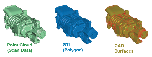
The most common step after raw 3D scan data is captured is to create a reverse engineered CAD (computer-aided design) model. CAD models are digital 2D and/or 3D representations of a part, or of an assembly of parts, that include the intended shape and object properties saved in appropriate formats that allow for use in many different parts of a product’s design, testing, and manufacturing processes. Because of this, a product’s CAD model is one of the most critical components of new product development and production using CNC machining, additive manufacturing, injection molding, and many other manufacturing processes. Even after the physical parts are made with the help of the CAD file, this digital model is used to compare the geometry between digital and actual, verifying that the part is built as intended. That said, 3D CAD modeling can be made difficult when a part has many features or complex geometries that are tough to create in standard modeling software. Additionally, if the intent is to design a part to mate to something that already exists, it is extremely important to be able to measure and recreate the existing part in digital form as accurately as possible.
At Laser Design, we are experts in 3D scanning and reverse engineering to a level that focuses on providing the best 3D measurement technology for the part, along with the right deliverables for our customer’s downstream processes. There are numerous ways a CAD model can be used and we have reverse engineering solutions to fit all potentials based on the application specifics. Our experienced Sales Engineers want to learn as much as possible about each project’s requirements as it’s important for us to understand how each stakeholder will be using the 3D CAD model and what is critical to their success when working with the file we provide. Below are some examples of internal and external stakeholders and some questions that will help us to determine the right format for your reverse engineering project.
Stakeholders
- Internal departments (Research & Development, Engineering, Production, Quality, etc.)
- Manufacturing Outsourcing Partners (Contract Manufacturers, Prototyping, Materials Testing, etc.)
- Other Sub-Contractors (Product Design, Inspection, Advertising/Marketing, Visual FX, etc.)
Don’t know what file format is right for you? No problem…We Do!
If you don’t know what file format you or your stakeholder needs, that is not a problem. Our experienced team of sales engineers can determine what file format(s) are appropriate for your downstream processes based on the answer to a few simple questions.
Questions
- Tell us about your part:
- Size, shape, material, manufacturing process, etc.
- Share any images you can to help us visualize the item of focus
- What is the intended use of the file you’re looking for and who will be using it?
- What accuracies do you require in the reverse engineered deliverable and are there any critical surfaces or features that need more accuracy than others?
- What level of modification are you planning for with the delivered CAD model?
Deliverable Formats
Even though you don’t need to know all the different options available for a CAD model deliverable from Laser Design, or how to determine which is right for you, it’s nice to understand why we are recommending a specific solution to meet your needs. Below lists the most common reverse engineering deliverables that we’ve provided to our customers over the past 30+ years, along with details like the data type, available file formats, common part shapes, and typical applications.
Raw Point Cloud
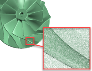 A raw point cloud is a set of XYZ data points that represent the 3D geometry of the object. These measurements are produced by 3D scanners and are considered to be the absolute “raw data”. Typically, this file format is for customers that already have CAD or inspection software to use for both form and dimensional analysis of the as-built part. As seen to the right, when points are captured with enough density, it can appear to be a surface, vs. a large number of points. In many cases, we’re capturing hundreds of thousands, if not millions of points on the surface of a part. The full scan of the impeller shown is made up of 2 million XYZ points.
- Data Type: Point Cloud
- Common File Formats: IGES, ASCII, PCN
- Best Part Shape: Organic, Freeform, Complex curvature
- Application: As-Built Analysis, Quality Control, In-House Inspection
“STL” Mesh
1. Raw Mesh
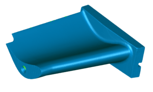 First, we should make you aware that many people refer to this format as “STL” as this is the most common file format used for mesh files in both the 3D scanning industry and additive manufacturing, not to mention finite element analysis and others. Like raw point cloud data, a raw mesh data set can come directly from the 3D scanning process, especially when using a structured light 3D scanner like the CyberGage360 or Artec portable scanners, and can be thought of as connecting each of the XYZ points with a line (digital connect-the-dots). With other 3D measurement technology, like 3D laser scanners and 3D computed tomography systems, this mesh file can be created from the raw point cloud or voxel data set respectfully. In any of these cases, the mesh files include a high level of detail of the physical part’s geometry and even include characteristics like shrinkage, warpage, and other deformations that may be found in the actual part based on the manufacturing process. This format of mesh can be used when you want to have access to the most accurate measurements of your part but need it in a mesh format for downstream processes like Additive Manufacturing, FEA Analysis or Inspection.
- Data Type: Polygonal Mesh
- Common File Formats: STL, OBJ, PLY, WRL
- Part Shape: Human Body, Organic, Complex Curvature
- Application: Art, Virtual Reality, Space Mapping
2. STL Converted from CAD
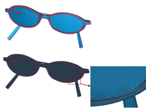 Another source of STL files are those exported from CAD. Unlike and STL from raw scan data, this type of file has mathematically defined geometry. For example, surfaces that should be considered “flat” will be flat. File sizes of this type tend to be much smaller than raw data meshes and are more appropriate for applications such as 3D printing.
https://www.laserdesign.com/3d-scanning-and-reverse-engineering-for-3d-printing-applications/
- Data Type: Organized Mesh
- Common File Formats: STL, OBJ, PLY, WRL
- Part Shape: Prismatic Shapes, Symmetrical, Repeating Features, Uniform Thickness
- Application: Rapid Prototyping/3D Printing
Parametric Modeling
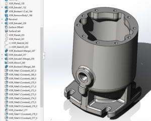 Parametric modeling is feature-based method that consists of various types of features such as grooves, holes, fillets, lofts, sweeps, and chamfers. A “feature” is a basic unit of a parametric model. The major advantage of a parametric model is the ability to change the shape of the model geometry as soon as the modeler applies a dimension value. Certain rules/relationships are applied to features to make modifications easier for users. For example, feature patterning ribs around a center bore with even spacing. The modeler can easily modify the number of ribs and spacing value if design changes are required.
- Type: Parametric
- Common File Formats: Solidworks, Creo, Catia, UG/NX, Inventor
- Part Shape: Repeating Features/Patterns, Symmetrical, Prismatic
- Application: New Product Design, Injection Mold Design
Non-parametric Modeling
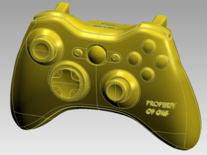 Very similar to regular parametric modeling is non-parametric modeling. Unlike the former, it does not consist of a design tree. This method sometimes requires use of imported bodies from multiple CAD packages during the modeling phase due to complex geometries that certain CAD packages have difficulty fitting surfaces to. A perfect example for someone needing a model that does not requires a parametric model is someone looking to scan the body of a car. With the complex geometry of the blended surfaces, a parametric model would not be needed due to the difficulty of the post modifications.
https://www.laserdesign.com/3D-Scanning-of-Electric-Car
https://www.laserdesign.com/duplicating-a-distinctive-glass-bottle-mold-with-3d-laser-scanning/
- Type: Parasolid, Generic Solid
- Common File Formats: STP, IGES, X_T
- Part Shape: Organic, Freeform, Complex Curvature
- Application: Hybrid Modeling, CFD/FEA, As-Built Design
NURBS Surface Modeling
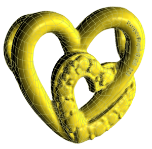 This method requires raw scan in point cloud or mesh format. For point cloud, the points will to convert to a triangulated mesh. Often times, a mesh prep wizard will be required to help repair any triangles that may have intersections. The purpose of this method is to keep the deviation between CAD surfaces from original 3D scan data as small as possible. This is possible by applying contours, grids, patches, CAD surfaces directly onto the scan. This method is perfect for quality engineers that are looking for a 3D digital file to analyze.
https://www.laserdesign.com/4-easy-steps-to-nurbs-surface-modeling-in-geomagic-design-x/
https://www.laserdesign.com/3D-Scanning-Provides-High-Quality-Data-of-Custom-Electric-Guitar
- Type: Surface Parasolid
- File Formats: STP, IGES, X_T
- Part Shape: Human Body, Organic
- Application: Art, Ergonomics
How 3D CAD Modeling Can Streamline Your Project
Whether you’re new to the 3D scanning process or have a bit of experience, leave it up to the experts to ensure you get the most benefit from this versatile technology. Some of the largest benefits to using a 3D CAD model include more efficient workflows and increased design productivity. Additionally, using the 3D CAD model for performance simulation, analysis, and verification can help avoid costly mistakes in design, production, or even with real-world part performance. Modifying or creating multiple revisions in 3D CAD software will save you time and money compared with physical testing, manual rework, and lengthy defective part analysis processes.
