At Laser Design, laser scanning technology has been adapted for a variety of high-tech solutions to common challenges faced by manufacturing companies around the world.
How does laser scanning work?
Rapid Profile Sensor
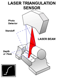 The essence of the system resides in the laser sensor, called the Rapid Profile Sensor, or RPS. The line range laser sensor collects thousands of points of data per second, making digitizing significantly faster than conventional noncontact measuring technologies without sacrificing accuracy. Line range means that the laser beam is spread out into a plane with passive beam spreader optics which forms a line of light on the object being scanned. The sensors in the probe take measurements over the whole line at the same time instead of measuring just one point of light, as with a point range sensor. This reduces scanning time dramatically.
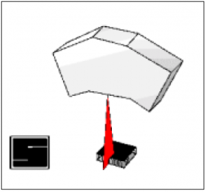
By using the principle of triangulation, the sensor gathers extensive part profile geometry quickly and precisely. The laser in the RPS probe produces a plane of light that intersects the part to be measured, as shown in the Laser Triangulation Sensor drawing.
The sensor is positioned at an angle to the laser plane so that a profile of the part is imaged as a line on the sensor’s two-dimensional CCD photo array. The image is digitized in the probe’s sensor control board and the raw data are sent back to the video processor (VP) board in the host computer. The video processor reduces the image data to parameters that the laser software can convert to coordinates in the probe reference frame.
Raw data are made up of gradient values of the charge in each pixel of the CCD array. Subpixel interpolation is performed either in the software or in the VP board. The resident laser software controls the probe settings and converts the data points to 3D coordinates.
Surveyor Systems and DataSculpt Software
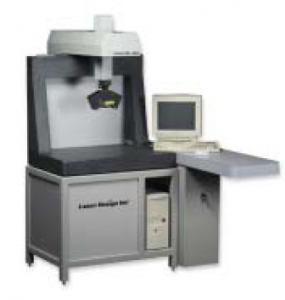 The RPS lasers are mounted on complete scanning systems, the LDI Surveyor systems. The Surveyor 3D laser digitizing systems come in a variety of sizes to fit most scanning applications, large and small. The economical Surveyor 1200 systems fit conveniently in areas with limited floor space and consistently provide linear accuracies of .0005″ (.0127 mm). The Surveyor 3200, with a work envelope of 40” x 40” x 32” (XYZ), and the Surveyor 6000, with a work envelope of 100” x 80” x 60” (XYZ), provide similar accuracies for larger parts. All systems are controlled by LDIs proprietary software, DataSculpt with Scan Control, that creates a flexible digitizing environment and can handle the complexities of Surveyor system enhancements such multiple rotary tables, four- and five-axis index heads, and touch probes.
One consistent interface in DataSculpt allows operators to use its tools and techniques to define scan regions, set up automated scans, and also to edit the resulting data, which greatly reduces the time spent in software training and doing projects. User-specified tolerances precisely control scan speed, pattern, and density of the scan. Advanced macro programming capabilities customize the user interface and automate repetitive scanning and data processing tasks.
What does laser scanning do?
Rapid Inspection and Verification
Designcraft, a service bureau in the Chicago area, that makes engineering prototypes, industrial models, 3D CAD models and computer models, recently used the Surveyor 1200-24 system to scan large steel castings for finite element analysis (FEA) and to update blueprints. Over time, changes made to the foundry patterns in the shop had altered the dimensions of the castings significantly. Although the castings were still functional, the shop could not tell what had been modified because the original blueprints had never been revised.
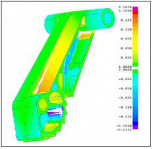
The castings were scanned using several different angles to capture the undercut surfaces, then the scan data was imported into Imageware for surfacing. Once the surface was complete and closed, a solid model was made and the data was used to perform a FEA to simulate stresses in the part. Designcraft was able to structurally analyze the extant version of the steel castings and make new CAD drawings to reflect the current design. This saved the casting maker significant time and engineering cost, and resulted in a much more accurate stress analysis than would have been possible using CAD-generated, rather than real scan data.
Another company that uses the Surveyor 1200-24 system makes small plastic parts that need to be inspected and verified against CAD data. Fabrication tolerances have to be kept at .005” at critical locations for certain usages and for the parts to mate with other parts in the product. Laser scanning allows the user to quickly and graphically identify out-of- specification sites and standardize injection molded parts. The dimensions obtained from the data is quickly matched against the database to qualify parts and tools to molded parts.
Because of the rapid scanning speeds of the line range laser sensor used by the Surveyor 1200-24 system, the user saves enormous amounts of time in the verification process by digitizing the shapes of the small plastic parts it molds. The software automatically organizes part dimensions and highlights critical ones in reports, and the color maps make the results easy to understand for engineers and technicians alike. And a bonus: because most of the parts scanned are approximately the same size, the Surveyor system can automate the inspection process by using runfiles to scan parts unattended.
In-Line Inspection
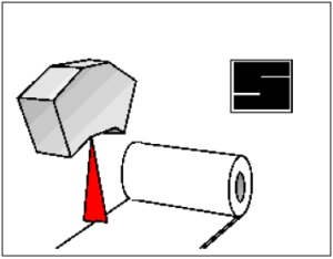
A brand-new variation to the rapid inspection theme is in-line inspection, that is, using one or more stationary laser probes to inspect a product on a production line. This kind of setup can be used to check the consistency of a profile, the spacing or width of features, the height of a contour, all while the part is moving past the laser at a steady rate.
 Above right, the illustration shows how probes mounted on an automobile assembly line can inspect and measure the door gap to ensure evenness and uniformity.
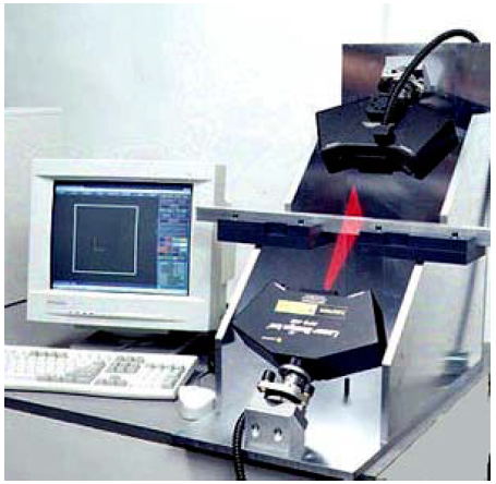 Xerox Corporation is making an investment in this kind of fast, accurate in-line inspection application with a newly designed system from LDI. According to LDI’s system developers, the system will be used for continuous inspection of the 2D shape manufactured by Xerox plastic extrusion lines. This continuous in-line inspection system has two RPS probes in series. It is accurate to approximately .001”, provides shape profile measurements at speeds of up to 14,400 points per second.
This low-cost 2D profile inspection technology represents a revolutionary breakthrough for in-line inspection of complex extruded shapes in terms of efficiency and cost- effectiveness. The LDI system scans at speeds of up to ten times faster than the best competition at approximately one-tenth the cost.
Reverse Engineering / Rapid Prototyping and Manufacturing
Surveyor 3D laser digitizing systems with the Rapid Profile Sensor collect 3D scan data of objects from multiple orientations, typically at a speedy rate of 4,000 points per second. DataSculpt software then assembles the various orientations into a common coordinate system. In this way data can be created for a prototype model or for a part for which no CAD/CAM data exists.
Advanced editing tools reconstruct planar cross sections in the new reference frame and character lines and surface region boundaries are identified. The data can then be output to normal 3D CAD software for surface or solids modeling.
Back at Designcraft near Chicago, several reverse engineering/rapid prototyping and manufacturing projects have been successfully completed in this manner. The companywas charged with generating a CAD model of a joystick base model which had been sculpted by a designer from clay and foam. The CAD data would then be used to engineer the internal components for the joystick base and to make tools for injection mold of the finished joystick.
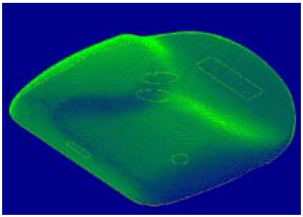 Making a soft joystick base model allowed the designer to ergonomically contour the shape to fit comfortably in the end user’s hand. However, soft, pliable materials are notoriously hard to duplicate using any contact measurement methods. Noncontact laser scanning was the ideal solution for gathering data that precisely defines the shape of the joystick casing.
After the joystick base shape was established, the model was scanned from one view and the resulting data edited. The model was surfaced and a CAD model created, which the CAD department used to insert and fit internal components into the housing, all on-line.
DataSculpt allows three-axis CNC toolpath generation direct from 3D scan data files, accelerating mold/tool/die production and CNC carving applications. Core and cavity toolpaths for many types of cutters can be produced from a single set of scan data. Designcraft used this facility to cut a hard plastic model on a CNC machine. Eventually, the data which exactly replicated the design, was used for production tooling and to produce a drawing that saved the company 50% of normal CAD rendering time.
Laser Scanning for the Future
 LDI has been a leader in the field of manufacturing 3D laser scanning solutions since its founding in 1987. The company’s patented line-sensor technology dramatically reduces scanning time by collecting data substantially faster than possible with conventional measuring technologies. Surveyor 3D laser digitizing systems quickly and accurately measure parts of all sizes, especially those with complex geometry.
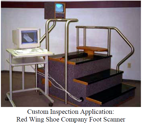
Rapid inspection and verification applications, including process control and in-line inspection promise to be a major consumer of laser scanning systems in the future. Reverse engineering / rapid prototyping and manufacturing applications also continue to appropriate a good share of the business. Because of the technology’s versatility, several custom applications have been developed, such as the foot scanner (shown below) recently completed for Red Wing Shoe Company of Red Wing, Minnesota. DataSculpt and Imageware software packages allow quick and versatile data gathering and data manipulation for all applications.

