 The Company:
The Minnesota company is a leading manufacturer of high quality ATV, snowmobile and motorcycle parts and accessories. Serving both OEMs and the aftermarket, the full-line manufacturer offers everything from product development and design engineering to complete steel fabrication, including stamping, tube bending, robotic welding and assembly.
The Challenge:
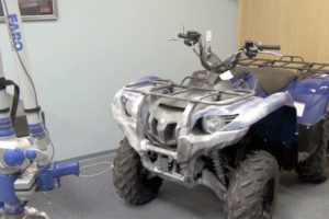
The company designed and manufactured a prototype snow blade for the Yamaha Grizzly ATV. Previously, to mount it they had measured the mounting locations by hand. However, they oftentimes found that the mounting holes on the blade interfered with the free-form plastic grille that enclosed the front of the ATV. In fact, interference when mounting items to the vehicle led to a lot of design rework on many of the accessories and aftermarket parts the company manufactured. The company needed a faster and more accurate way to capture the ATV’s geometry for their part design and development process.
This assurance of valid results enabled the company to revise some of their other accessories and make adjustments to assure a perfect fit in the future, saving them both time and money.”
 The Solution:
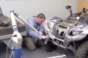
The company contacted Laser Design Services Corp. to 3D scan the ATV completely and accurately. Rather than having to measure piecemeal by hand, their team would be able to use the digital model to precisely position mounting holes and other features to correctly fit with the vehicle. The laser scanning system projects a line of laser light onto all of the part’s surfaces while cameras continuously triangulate the changing distance and profile of the laser line as it sweeps along. Non-contact scanning means that the problem of missing data on a complex free-form part such as an ATV is greatly reduced. Laser scanners measure articles quickly, picking up to 75,000 coordinate points per second, and generate huge numbers of data points without the need for special templates or fixtures.
Laser Design engineers laser scanned the entire front end of the ATV (position 1, including structural portions and aesthetic features like the fenders) using the Laser Design FA system with the 12’ Platinum FaroArm® and the SLP-2000 line laser probe along with the 1/8” carbide touch probe for specific landmark features. The SLP-2000 offers a super-long 240mm (9.8”) laser line for faster scanning with better coverage than most portable scanning systems on the market today. This laser probe also allowed scanning into the frame without removing the plastic grille which made the scan more accurate and much faster. The same FaroArm setup was used to touch-probe the mounting hole locations on the vehicle.
A second setup was used to scan underneath the ATV (position 2). After the top and front were scanned, engineers removed the skid plate and lifted the vehicle off the ground to scan the bottom of the frame about halfway back. With the precise touch-probed data of the mounting holes from the previous setup, engineers were able to merge the data from the second setup with only insignificant error. The accuracy of the laser scanning was ±.005”; the touch probe accuracy was ±.002”. Since the two set-ups were merged within ±.002”, the overall error was held to less than .005” for the entire data set. The setup and scanning took about 4 hours, including the scan in position 1, the removal of the skid plate, lifting the ATV, and the scan in position 2.
 The Results:
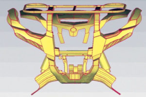
The 3D scan reproduced the ATV profile completely and precisely in the coordinate point cloud. The native software (Surveyor Scan Control) automatically connected the data from the multiple views into a common coordinate system in a single 3D scan file. This data was processed and modeled in Rapidform to create a CAD model including parametric, solid, and imported mesh modeling features. The final deliverable was a SolidWorks native model exported from Rapidform that contained solid mounting features, and NURBS surfaces for the plastic on the grille and fenders. Modeling time was about 6 hours. Turnaround time for the whole project was only 3 business days.
As the company had realized before contacting Laser Design, measurements taken by hand were much sparser, never really capturing the totality of the shape and lacking the required accuracy. Without the speed and precision of non-contact laser scanning, this type of exact true-to-life shape replication of large items would be virtually impossible.
The resulting solid model of the frame and mounting locations and the dumb NURBS surface model of the plastic grille could be imported into a CAD package such as SolidWorks. This allowed the company to design parts and accessories around the existing ATV geometry and double-check all of their clearances, avoiding costly reworks after the fact. The very accurate locations of the mounting holes ensured that the snow blade and other accessories could be designed without interfering with the plastic grille, and that the parts would fit correctly every time.
An interesting test of the scan data’s accuracy arose when the company tried to fit the CAD model of one of their known working parts to the CAD model of the ATV and found that it did not fit correctly. The designers suspected an error in the scan data. However, Laser Design engineers suggested that they try mounting the physical part to the actual ATV to verify geometry. When the company designers did this, they discovered that the part did not, in fact, mount well on the vehicle. Annoying as this discovery was to the company, it reinforced the evidence that the Laser Design CAD model was very reliable and could be used to predict fit problems without having to actually manufacture a part or try the part out on the real ATV. This assurance of valid results enabled the company to revise some of their other accessories and make adjustments to assure a perfect fit in the future, saving them both time and money.
