 The capabilities of Laser Design spans the gamut from high-accuracy reverse engineering services to 3D CAD model creation to product design and development to testing and analysis. This project for an optics company involved all of those phases – full engineering services to bring about a successful product launch.
The Company:
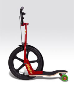
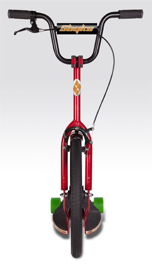
The company based in the U.S. Southwest makes innovative optics for racing cars and other extreme vehicles. Recently the owners, who grew up in Southern California’s skateboard culture, came up with a new product idea for a kick scooter, mainly for kids, based on the design of a skateboard. The company applied for the worldwide patent in 2007. It was approved in 2009 and they soon began the serious product design and engineering phase of creating the scooter.
PHASE I –Designing the Deck
The Challenge:
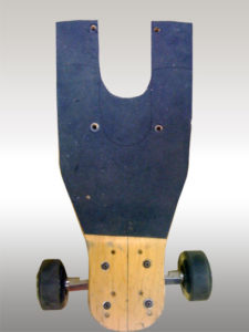
The owners realized that the quickest way to develop a product based on an existing one was to obtain a three-dimensional model for that existing object, in this case, an off-the-shelf skateboard deck. They could then reverse engineer the deck shape incorporating their design changes easily in the CAD data.
They had heard of 3D laser scanning and thought it was a great idea, but did not have any connections in the industry. Internet search results produced Laser Design at the top of the list and conversations with the Laser Design account manager confirmed that Laser Design could do the job accurately, quickly, and cost effectively.
The hand-modified wooden skateboard deck that Laser Design engineers would scan was quite rough and not completely symmetrical, so the subsequent digital modeling process would need to make corrections to the scan data, bringing the solid CAD model back to the design intent.
 The Process:
The service engineers used the Laser Design SURVEYOR™ WS-2030 3D laser scanning system with the high-accuracy Laser Design SLP-500 laser-line scanning probe (with accuracies of up to 0.011mm and 0.005mm resolution) to precisely scan the skateboard deck’s irregular profile. Because the laser scanning system projects a line of laser light onto all of the part’s surfaces while cameras continuously triangulate the changing distance and profile of the laser line as it sweeps along, the problems of missing data on irregular surfaces are greatly reduced. The laser line moves back and forth over the part’s surface until the complete area is captured digitally. The system measures details and complex free-form geometry so that the object can be exactly replicated digitally. Laser scanners measure articles quickly, picking up to 75,000 coordinate points per second, and generate huge numbers of data points without the need for special templates or fixtures.
The Surveyor system’s native software, Surveyor Scan Control (SSC), took only a few minutes to set up. The desired scan data density was predetermined by the operator. Even though the pre-processed raw data of the skateboard deck comprised over 2 million coordinates, the actual amount of data collected is much greater. The SSC software has a filtering feature that eliminates redundant surfaces during the scanning process. The resulting point cloud is a totally comprehensive representation of the part. Usually millions of coordinates are kept to adequately define the part being scanned for either reverse engineering or inspection. A typical scan density for this type of part is 50,000 to 100,000 points per square inch, but almost any density can be preset by the operator.
Scan time for the skateboard deck was approximately 1 hour. Without non-contact laser scanning, capturing enough data coordinates to accurately define the deck’s curved irregular shape could have taken 20 times longer, and would have resulted in a much less complete data set. Measurements taken by hand would have been much more sparse, never really capturing the totality of the shape. And without the scan data, there is no way to verify whether the model is indeed correct, or by how much is it off. In the past, STL development would have cost $5000-$6000 for the scan alone. Today Laser Design’s scanning experts work so efficiently and accurately, the company realized almost 90% savings by using the laser scanning process.
After the 3D laser system scanned the entire skateboard deck, the native SSC software automatically connected the point cloud data from multiple views into a common coordinate system in a single scan file. An STL file was created which revealed the irregularities in the off-the-shelf product: the left and right sides were not symmetrical and the bottom was bowed left to right in the cut-out zone. These problems were easily corrected by Laser Design modelers in the solid model.
The Results:
Laser Design created a parametric solid CAD model in SolidWorks so they could produce a rapid prototype from the STL file. Laser scanning is ideal for reverse engineering complex parts to create STL and/or CAD models because the whole surface of an object is scanned, not just a limited sample of discrete points like in contact measurement. Parts can be modeled “as is” for exact replication or, as was the case with the skateboard deck, the original design intent of the prismatic shapes can be extracted even if the as-built part is warped, misaligned, or broken, typical for mass produced products. When taken into a parametric modeling CAD package, the “history” of the model is available to designers, so any version may be referred back to at any time in the re-modeling process. Design changes or variations can then be easily made. The reverse engineering part of this project was so successful, both in terms of usefulness of the model and cost-savings, that the company owners then asked Laser Design to help them with further steps in the product design process.
When an object is hard to measure manually or with a touch probe due to its irregular surface contours, non-contact 3D laser scanning can produce accurate CAD data very quickly. Once the designers examined the STL model, a few cosmetic alterations in the design were easily made in the CAD data to reshape the nose of the deck. Subsequently, Laser Design used the scan data to create parametric CAD models in SolidWorks incorporating dimensions for the molded blank, the hole locations, and the perimeter profile.
Laser Design helped the company obtain a rapid prototype from RedEye, a partner company of Laser Design. RedEye created an ABS plastic prototype skateboard deck with a sparse fill because it was lightweight and used less material at one-third the cost of a solid ABS model. The lightweight prototype allowed the company’s designers to see the errors just as well as the expensive version; the shape of the new design changes were verified easily via the prototype.
Because laser scanning is such an efficient method to obtain accurate 3D data of complex shapes, the whole deck design and development process took only a couple of months to complete, versus many months with traditional manual measurement methods and 2D design drawings.
The company was very satisfied with both the customer service from the account manager and the scanning results Laser Design engineers. So satisfied, in fact, that they contracted with Laser Design for a more complex process to further develop the scooter product and bring it to market: Finite Element Analysis of the metal frame.
PHASE II – FEA Testing the Frame
 The Challenge:
Field testing of prototype scooters revealed that some yielding was occurring in specific areas of the frame which compromised the alignment of both the handle and the wheel with respect to the frame. This was not only a concern from a mechanical standpoint, but also from a safety one. As a child’s plaything, assuring safety was very important to the designers and certain stress standards needed to be met. After trying several versions of a frame assembly, the company owners wanted to determine the type and thickness of the sheet metal in the frame required to stiffen the structure adequately. The metal strength and thickness should be enough to prevent excessive flexing and permanent set in the Z-frame without the need for beads. It was determined that Finite Element Analysis (FEA) testing could be used to measure stress and safety.
The Procedure:
As in the previous project phase, Laser Design engineers used the Laser Design SURVEYOR™ WS-2030 3D laser scanning system with the high-accuracy Laser Design SLP-500 laser-line scanning probe (with accuracies of up to 0.011mm and 0.005mm resolution) to scan the complex geometry of the prototype scooter frame. When an object is hard to measure manually or with a touch probe due to its free-form contours, non-contact 3D laser scanning can produce accurate CAD data very quickly. The prototype Z-frame’s sheet metal thickness was .125” (3.175 mm) and had two strengthening “beads” running along the sides. Although needed to create a functional design, the material’s strength properties made it the most expensive sheet metal choice.
SSC software automatically connected the point cloud data from multiple views into a common coordinate system in a single scan file. Then Laser Design created a parametric solid CAD model in SolidWorks to be used in the FEA. The original model was then converted for use in the FEA software and alternate metal thicknesses were variables programmed into the software.
The Results:
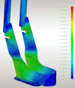
When FEA stress tests were run on the model, Laser Design engineers found that the sheet metal Z-frame with the .125” thickness (model 1) showed significant yielding and thus misalignment with respect to both the handle and the wheel, just as they had experienced in the field. The Factor of Safety was 1.0.
 Stress values were reduced with the introduction of the strengthening beads on the same thickness Z-frame (model 2), which had been proven in the field. The beads made the frame much stiffer and flexing was also decreased. No permanent deformation occurred and the Factor of Safety increased to 1.01. However, the scooter company did not want to use beads on the Z-frame in their design because it was cosmetically objectionable and because this type of sheet metal was much more expensive than the other ones tested.
The third FEA stress test was run on a Z-frame of .138” thick sheet metal (model 3). Though stress in one area of interest was higher compared to that area in model 2, it was far below the yield strength of the material and therefore produced no permanent set. The Factor of Safety inched up again, to 1.73.
Lastly, a model Z-frame of .157” thick metal without beads (model 4) was tested. Stress in all regions was well below the yield of the material; displacement showed only elastic deformations. The stiffness and amount of flexing of this frame were similar to the beaded frame (model 2). With double the original Factor of Safety, 2.18, model 4 was clearly the strongest Z-frame without beads, and the increase in mass was not significant when compared to the frame made of .125” thick sheet metal.
The company owners decided to use the .157” thickness sheet metal to fabricate the Z-frame portion of the assembly. This material met their strength, resilience, and safety requirements while reducing their manufacturing cost.
The full spectrum of Laser Design’s engineering service once again saved the company time and money both in the product development phase and in the manufacturing processes. The speed of laser scanning plus the expertise of Laser Design engineers in FEA testing and familiarity with the product resulted in fast, continuous service from professionals who had a deep multi-layered understanding and experience with the breadth of the entire project.
