 Article first appeared on SME’s Advanced Manufacturing
The question of how users can compare accuracy of one device to the next remains challenging
Aircraft manufacturers are finding noncontact metrology ever more useful. Its inherent high throughput and decreasing cost is complementing the industry’s ramp-up to meet the world’s appetite for more airplanes. However, throughput needs to be balanced with accuracy in finding the right applications as noncontact embraces a variety of devices.
“Noncontact metrology is either laser or optical based,” said Eric Nemitz director of sales North America of Automated Precision Inc. (API, Rockville, MD). “Typically, 3D laser metrology scans a line over a part, or the part is moved under the line.” Optical systems use one of a variety of multiple images and triangulation, typically photogrammetric systems or today more commonly fringe projection techniques ubiquitously known as white or blue light scanning. “A laser-based system will always be attached to a globally aligned device, such as a CMM, a portable arm, or a robot referenced by a laser tracker,” Nemitz said. White light scanners are also often attached to a movement device and usually require registration marks on the part or on fixtures to achieve the highest accuracies.
While noncontact has its advantages, so too do traditional touch trigger or scanning analog probes. It is all about accuracy and shape. “Prismatic features—circles, holes, slots, plain line points—have very tight tolerances and are generally best served by contact measurements. These are applications that typically need to be measured to less than 20 μm, which only probes can deliver,” Nemitz said. Noncontact systems, on the other hand, typically have accuracies of 50 μm or greater, but are ideal for nonprismatic or organic shapes. “Wing spans, plastic parts, leading and trailing edges, turbine blades—parts that need a lot of data to define them are ideal for noncontact measurement,” he said.
New Technologies, Faster Collection
Another key element is speed. Everyone wants to make measurements more automated and noncontact techniques typically provide high data rates, up to millions of points per second. White light systems, while fast and accurate, have some disadvantages, such as the need to coat parts and deal with reflective surfaces. To alleviate some of these issues, API has introduced its RapidScan optical scanning device featuring infrared light rather than visible. Surfaces are less reflective in the longer IR wavelength and less susceptible to ambient light.
Nemitz also noted that API’s RapidScan system uses a camera with a higher dynamic range than is typical, 50% higher db. “This allows us to take a highly reflective part and capture more intensity,” he said. “For example, with a lower db system, the reflectivity will bleed out the points and you will get zero data. The higher db system will capture data.” This provides an additional advantage, the ability to vary the resolution. “With that, we can accurately extract prismatic shapes embedded in organic shapes, like holes and critical edge profiles,” he said.
Projection back onto parts of the results of measurements from fringe projection optical scanners, as compared to CAD, is useful in a number of aerospace operations.
With speed balanced with accuracy so important, other metrology providers, such as Hexagon Manufacturing Intelligence (North Kingstown, RI), are taking a fresh look at CMMs. “A good example of this is the Global Advantage HTA, designed specifically for fast aero engine blade measurements,” said Joel Martin, laser tracker product manager, Hexagon Manufacturing Intelligence. By placing an accurate Hexagon HP-O laser sensor on the Global Advantage CMM, the combined system can achieve accuracies as good as 5 μm in a gage block length measurement test, according to the company. The HP-O collects at a rate of 1000 points/second, much higher than a scanning analog probe. Martin noted that GE Aviation was an early development customer, citing data that showed GE measured 55% faster throughput than with traditional touch probe or scanning analog CMMs.
 Automation and Visibility
“I have seen the use of noncontact metrology increase steadily since 2010,” said Miles Molnar, applications engineer for Capture 3D (Costa Mesa, CA). He said that manufacturers are using fewer gauges, contact probes and CMMs equipped with touch probes in favor of noncontact. “In engine parts, we are talking about turbine blades that have very tight features and need high accuracy,” he said.
Capture3D is the North American reseller of ATOS systems from GOM, one of the pioneers of fringe projection metrology. He attributes its growing use to the increasingly capable accuracy and resolution of noncontact in general and ATOS systems in particular. He said that the most popular device they deliver to aerospace manufacturers is the ATOS triple scan. “That is our highest-end sensor, ranging from 5 million to 16 million pixel systems. The 16 million pixel version allows us to scan very small features much faster and quicker,” Molnar said.
Why is noncontact now so capable? Molnar said it is a combination of better optical components married to better cameras, lighting, software and cheaper, faster computing. “All of these components have increased exponentially in capability in the last five years,” he said. He points to more capable software in particular, as a key enabler. For example, the GOM-supplied Inspect Professional software package can help automate data collection and inspection routines, with a package created especially for airfoils. “You can take a section of your 3D scan data and extrapolate from that all of the needed airfoil callouts, such as leading- and trailing-edge diameters, chord length, twists and other important parameters,” he said.
Another useful tool unique to white light systems is the ability to project back onto parts the results of inspections, highlighting areas that are over or under tolerance as measured against a CAD reference. He believes this is especially useful where manual grinding or hand layup operations are needed.
A high fidelity ATOS triple scan device scans a turbine blade inside an automated system provided by Capture3D.
Hexagon also now has a structured light offering especially useful for aerospace applications, according to Martin. Hexagon acquired AICON 3D Systems, the inheritor of the Breuckmann fringe projection technology. Its main differentiators are its data quality and accuracy, resulting from dual high-resolution cameras and very adaptable data acquisition software. It complements Hexagon’s existing WLS fringe projection technology, whose collection rate is much faster. This makes the WLS ideal for applications where environmental stresses make a data collection measured in hundredths of a second good for countering vibration. However, the resulting data set might have more inherent noise than data collected in a much longer period, say a second or two, such as the AICON system. Another plus with the AICON solution is its full-color backprojection, making it easier to distinguish over and under tolerance areas. “The AICON product has translated well into aerospace, with its data quality ideal for inspection, reverse engineering and surface recreation,” Martin said.
Laser radar is another noncontact technology that has found a place in aerospace. A good example is the MV330 line of scanners from Nikon Metrology (Brighton, MI). Instead of a line, it bounces a focused infrared light beam off a surface to measure range, according to Peter Morken, senior applications engineer for Nikon. He cites five attributes for laser radars in general—noncontact, automated operation, precision, large volume measurements and portability. A laser radar’s accuracy is range dependent, the farther away the part, the less accurate. “At a range of 5 m [the MV330] is capable of measuring to 50 μm or 0.002″, to 2 Sigma,” according to Morken.
“Aerospace has been an early adopter of Laser Radar,” Morken said. “Individual parts up to subassemblies and major assemblies are measured by OEMs and subcontractors using laser radar.” While providing large-scale metrology measurements, a distinct advantage of the laser radar in particular is its ability to measure from a distance. While working on the F-35 program, he took advantage of this by using a laser radar to monitor a critical machining process, placing the device inside the machining enclosure. “This offered a completely external check of the entire machining process,” he said.
Changing Requirements, Measuring Accuracy
As marketers often say, perception is everything, and 3D noncontact metrology has ridden a wave of acceptance in just the last four to five years, according to C. Martin Schuster, CEO for LaserDesign (Minneapolis), makers of high-accuracy laser scanners. LaserDesign provides individual scanners, both the XLP and SLP line of scanners, as well as integrating them into CMMs and cabinets. “The data has always been accurate, but now manufacturing engineers and quality personnel are accepting the data. It is no longer a novelty,” he said. “We have done that by proving to be better than, or faster than, existing technology, which has typically been touch probes on CMMs.”
This acceptance also comes at a time when there are not only more airplanes needing to be built, but more inspection required as well. “We have heard from some of our customers that the FAA is mandating up to eight times more inspections than in the past to provide in-process inspection of batches,” said Schuster. He notes that there are some turbine blade manufacturing companies that have over 100 CMMs at a single location to keep up with the demand for 100% in-process inspection.
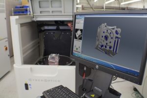
Laser Design Inc. offers the CyberGage360 3D Scanning and Inspection System. Powered by Laser Design’s parent company CyberOptics’ Multi-Reflection Suppression Technology (MRS), a full 3D volumetric scan and output report can be generated in less than 3 minutes—with simply one click of a button, according to the company. For part volumes of 200 mm D × 100 mm L (8 × 4″), the CyberGage360 measures to a system volumetric maximum permissible error (MPe) accuracy of 10 μm + L/10,000 mm (per ISO 10360.)
Accuracy specifications in terms of an adapted ISO standard written for CMMs equipped with touch probes can be done, but Schuster points out that such a specification is not well suited for a noncontact technology. “ISO 10360 is based on measuring from point to point, but scanning measures the entire shape of the part—it measures the mating surfaces and how the part functions,” he said. What is needed, he said, is a standard methodology to measure against the ISO 17450 GD&T standard, which measures form and function.
