A Powerful Scanner in a Small Package

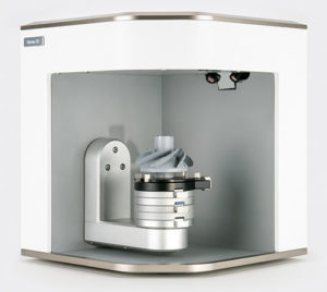
Artec Micro with tilt and turntable
3D scanners have come a long way in their 30+ year history. With parallels to the development of the first computers, the first 3D scanners were comparatively giant machines compared to the small handheld scanners that exist nowadays, such as the Artec Space Spider and Leo 3D scanners. Unlike their PC counterparts however, large machine-like 3D scanners still have a bona fide use in common 3D scanning applications. For example, the highest accuracy 3D scanners require a method of vibration-dampening, usually achieved through a sturdy granite table. As a result of the need for these large granite tables, the 3D scanner footprint takes up a space as large as a dining room table, despite the optical scanning hardware being very small.
As the progress of technology has marched on, the goals of achieving 3D scan data with +/- 0.001” or better accuracy has been left to the larger machine with the big sturdy granite tables, however a new breed of desktop 3D scanners has emerged with the Artec Micro at the forefront, the kind of 3D scanner that combines hardware and software to generate ultra-high resolution 3D scans with better than +/- 0.001” accuracy, all while taking up about as much space as a toaster oven. The future is now.
How It Works:

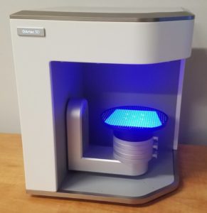
Calibrating the Artec Micro
The Artec Micro works very similarly to the Artec Space Spider 3D scanner: a semi-automated structured blue-light 3D scanner designed for small parts with high resolution. Unlike the Space Spider, the Micro is designed to capture the maximum level of detail from as few frames of data as possible, and in order to do this, the Micro uses 2 forms of hardware object positioning: one turntable, and a tilting arm. The Space Spider thrives when redundant data is captured from many different angles, however the Micro is designed to work with a smaller number of higher resolution frames of data. For comparison, an object 3D scanned with the Artec Space Spider might have 2000+ frames of data, where a comparable Artec Micro scan might contain 80 frames of data.
Artec’s proprietary software goes a step beyond by using A.I. to automatically determine the optimal path plans. Gone are the days of stressing over the turntable rotation degrees (for example, deciding if rotating every 30 degrees, 15 degrees, or 7.5 degrees is best). While you can still manually set paths for the Micro, the power lies in the ability to allow software to determine the most optimal rotation and tilt angles and maximize coverage while minimizing human error.
Recurring calibration of the Micro is useful, and a calibration block and software button are provided. The process is only a couple minutes long and does not require much effort. It’s easy!
Setting it Up:

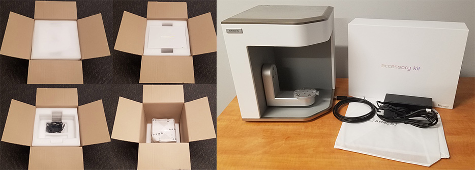
Unboxing and Components
The Artec Micro scanner will arrive in a well-packed wooden crate. Inside the crate, surrounded by foam padding, is a cardboard box containing the Micro. The Artec Micro is designed to hold accuracy tolerances tighter than +/- 0.001”, so It is very important to carefully remove the Micro and avoid banging on the crate and/or box too impactfully.
Once removed, the Artec Micro should be set up on either a standalone desk or platform. If no standalone desks exist, please position the Micro close to the sturdiest part of the table, usually near the legs. The rotation and tilt arm of the Micro may wobble or sway an un-sturdy table during scanning, and in worst case scenario might cause a loss of accuracy of the scan or wobble of the part being scanned. If this does occur, software processing will be used to fix any problems in the raw scans.
The Micro comes with a small instruction booklet showing how to set up the scanner on the PC, and a support guide can be found on Artec 3D’s website.
A brief installation guide:
- Connect the Micro to the power supply and plug into an outlet first
- Plug in the USB cable to the Micro, and then to the PC
- Turn on the PC
- Turn on the Micro (power switch in the back)
- Activate the Micro (if needed) in Artec Installation Center
- Perform calibration process
On modern PCs, driver installation is automatic. On some occasions, new drivers and updates to the graphics card, USB controllers, or BIOS may be helpful.
Best Practices and Tips/Tricks:
The Micro produces data that is very familiar to an existing Artec Space Spider user, and many of the best practices apply, however there are some nuances that should be kept in mind. Here is a short list of pitfalls, best-practices, and important considerations when scanning with the Micro:
Pitfalls:
- The data is extremely high resolution. Capturing too many frames of data will cause low end PCs to suffer from slow processing speeds.
- The movement of the turntable and tilt arm may “wobble” the table the Micro is positioned on.
- Do not lean on the table while the scanner is running.
- Parts you scan using the tilt arm may move when the tilt arm is at 90 degrees. Parts must be securely fastened to avoid the part changing position mid-scan.
- The Micro sometimes requires you to run “global registration” in order to generate the best quality data. Not having enough features of commonality (3D shape and colors) can cause registration errors.
- Capturing color is not enabled by default. To capture color, you must enable High Resolution mode first, followed by color data capture.
- Unlike the handheld Space Spider which allows an operator to freely reposition the scanner, the Micro requires more effort with the interface to capture the “perfect angle” on a shiny part. 3D scan spray is more useful and required to capture the best results with the Micro
- Using 3D scan spray in a regular can in a regular environment might cause small chunks of spray material to be ejected onto the part, resulting in an uneven spray application, resulting in a chunky looking surface finish to the scan.
Best Practices:
- Use a spray booth and/or a spray nozzle when using 3D scan spray to get the smoothest and cleanest application.
- After scanning, run global registration on each individual scan. You can then “Lock” those scans when aligning and registering with other global registrations.
- Use a high end PC with at least 32 GB of RAM, ideally 64 GB or higher
- Learn the manual path programming. Your part may require special and very narrow angles in order to capture deep pocketed areas. Learning how to manually set the turntable path is very helpful to leave no area un-scanned.
- Place the Micro on its own sturdy table and make sure nothing touches it or causes vibrations during the scanning process.
- Use a generous amount of “blue tac” (included in the Accessories Kit) as a moldable part holder to keep it from drooping down when the tilt arm is approaching 90 degrees
- Create a ring of blue tac around the part, like a mini “Stonehenge” of 3D shapes. This ring of additional geometry will help any global registrations that might be required after scanning. Scanning a complex part like a fossil might never require this, but a geometrically simple shape like a gage block would benefit greatly from extra geometry in the registration.
A guide of some example objects and their best practices can be found below:
| Noteworthy Attributes: Thin edged part, few occlusions, some shininess, minimal color Strategy: 3D scan spray not required. Create a ring of blue tac for registration. Scan from 2 positions: edged side up/down. Use Automatic path plan mode. |
|
| Noteworthy Attributes: Rich geometry, rich color, many occlusions, very dull color Strategy: Two “Automatic” scans from top and bottom sides. Simple registration -> alignment -> registration -> fusion is all that is needed. |
|
| Noteworthy Attributes: Flat geometry, single color texture, few occlusions, high shininess Strategy: 3D scan spray is required. Create a ring of blue tac for registration. Scan in at least 3 positioning: broad side up/down and key detail side up. |
|
| Noteworthy Attributes: Medium geometry, single color texture, few occlusions, dull surface Strategy: 3D scan spray is not required but very useful. Scan in 2 positions: blade up and blade down. Fixture in big lumpy mound of blue tac for maximum stability. Create a ring of blue tac for registration. |
Sample file downloads are available here >
Wrapping it Up
The Micro is an impressively easy 3D scanner to learn and use. Only a minimal amount of effort is required after scanning in order to produce a great model, and even less effort is required to set up the scan for success. It is often a great idea to imagine, “What could possibly cause this scan to fail?” as a way to troubleshoot unsatisfactory scans. Many of these possibilities are covered in the best practices and pitfalls section above. Please reach out if you have any questions about the Artec Micro – we’d love to help!
Happy scanning!
