Creating an assembly model of a GoPro® Camera Case
Over the past 30+ years, Laser Design has received many requests from our customers to support their 3D scanning and reverse engineering needs focused on measuring and creating 3D CAD of an assembly made up of two or more parts. Initial conversations focus on what the customer will use the deliverable for and progress into details that help us understand how we can successfully measure the parts to acquire the geometry in the proper assembly state for the project. Typically, non-destructive measurements are key to capturing the assembly in a constrained state to give us the best understanding of the shape of the assembly in a real-world state. Using 3D scanning technology, we’ve shown many customers how their parts can change shape after disassembling because physical constraints are removed. Reverse engineering an assembly requires a thoughtful approach from both the 3D measurement and the 3D CAD modeling perspective.
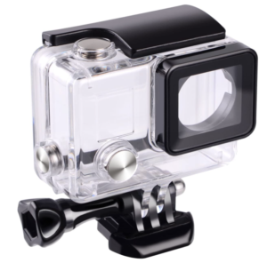
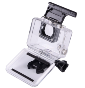
Luckily, with the help of the RX Solutions EasyTom CT scanner, Laser Design, a CyberOptics corporation brand, can non-destructively measure parts and assemblies in various states of constraint to capture the appropriate 3D data that supports successful reverse engineering applications. Providing metrology grade accuracy at appropriate resolutions to fit the application needs, the EasyTom is used for defect detection, visualization, dimensional metrology and reverse engineering applications. Below is a summary of how the EasyTom CT scanner was used to support a reverse engineering application of a GoPro® camera case/cover.
Multi-Material Surface Determination
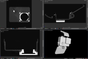
One of the major advantages of the EasyTom’s CT scanning technology is the ability to capture each component of a multi-material assembly based on the different densities of each component’s material make-up. Applying the proper acquisition and reconstruction settings will provide a 16-bit 3D voxel data set that can be used to accurately determine the surfaces of each component based on relative greyscale value. 16-bit translates into 65,536 shades of gray that can be used to represent each material type – this can be seen by the naked eye in many cases and software can be used to accurately isolate higher and lower density components based on the shades of grey of each component. In the case of the image below, air is represented as black (low density) and the materials of the GoPro® Case are represented as shades of grey and white based on their respective densities (highest density closest to white). With this type of information, we can segment and export 3D measurement data of each component in an easy-to-use 3D mesh format (STL) for reverse engineering. In this application, our engineers can easily understand the assembly makeup from the 3D CT scan data and verify the location and position of the higher density metal buttons and hinges in relationship to the lower density housing and the lens covers within the action camera case assembly. Scans can be taken in open and closed positions to understand the relationship between parts of the assembly in different states of constraint.
Reverse Engineering Mesh files
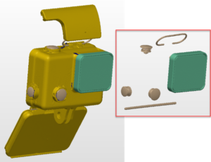
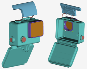
Once the mesh files are extracted from the voxel data set in STL mesh format, Laser Design’s engineers will use tools within reverse engineer software to accurately create the as-designed or as-built assembly models from the scan data. In this case, we used Geomagic Design X to create features and surfaces using the scan data as reference. This allows us to generate a very accurate CAD model of the assembly without guessing at the critical geometry that are important to our customers. The final model of this assembly is representing the as-designed geometry of the measured part and exported the CAD files as generic STP/IGS models. This as-designed 3D CAD model includes idealized shapes to portray the shape of the assembly when it was designed. This is accomplished by applying CAD modeling techniques like symmetry, uniform thickness, common feature geometry, and others. Along with neutral CAD formats like STEP and IGES, Design X also allows for LiveTransfer of geometry to major software packages that support creation of parametric features. Available file formats include:
- Solidworks (.sldprt, .sldasm)
- Catia (.catpart, .catproduct)
- Creo (.prt)
- Inventor (.ipt, .iam)
- Unigraphics (.prt)
- AutoCAD (.dwg)
Application Summary
-
- Benefits:
- Accurate representation of scans in constrained assembly state
- Non-destructive 3D scanning in single setup of part
- Ability to distinguish different material densities within assembly
- Understand mating relationship between subcomponents
- 3D CAD model provide in format to meet customer’s immediate and future needs
Related Links – Laser Design blogs, case studies and web content
- CT Scanning and Parametric Reverse Engineering
- Differences between as-built and as-designed reverse engineering
- Reverse Engineering Services
- 3D Scanning service bureau benefits
- EasyTom 150kV CT Scanner
‘Trademarks are owned by their respective companies.’
