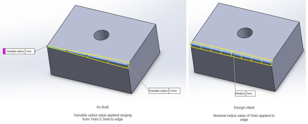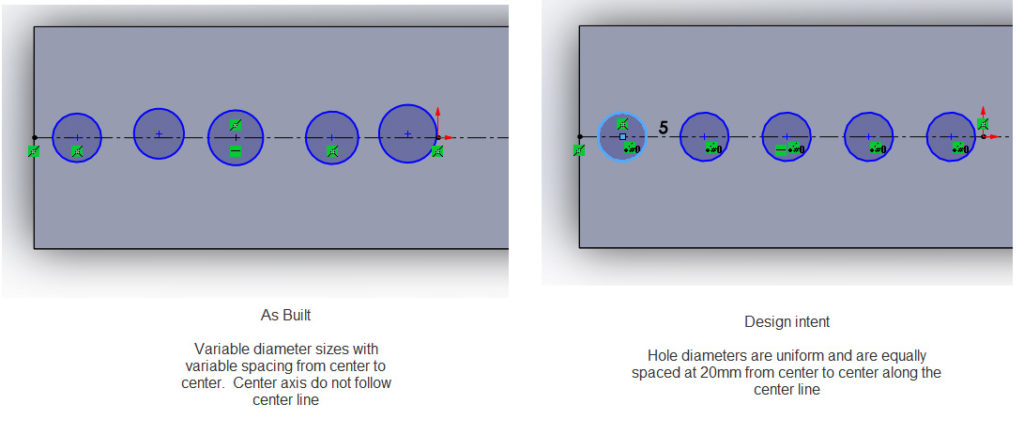
As-Built / Variable Radius value applied ranging from 1mm-5.5mm to edge (Left); Design Intent / Nominal radius value of 5mm applied to edge (Right)
Laser Design, a CyberOptics Corporation brand, has been a leading provider of 3D scanning and reverse engineering services for over 30 years. Whether your company is in the automotive, aerospace, defense, electronics, medical or any other manufacturing industry, the most important question to answer during a reverse engineering project discussion is if an “as-built” or “design-intent” CAD model is needed. By providing Laser Design with your project end goal and/or your downstream application requirements, our highly skilled and experienced technical team can explore the different options of deliverables and guide the project toward success.
Many customers we talk to communicate their assumption that a 3D CAD model is created during the 3D scanning process. For example, putting their physical part in a magic box and pressing a button to measure the 3D geometry and create a perfect CAD model ready for design, manufacturing or rapid prototyping applications. Even though the process of 3D scanning and reverse engineering have been greatly simplified over the years, it is not fully automated and there are still two main steps required to provide you with the CAD model that meets your expectations.
- 3D Measurements using 3D Scanner – Based on the part size and geometry, accuracy requirements, and application goals, our engineers will determine which measurement system is best suited to measuring physical part geometry using 3D scanning technology. The 3D scans will be collected either in point cloud (.asc, .igs, etc.) or mesh (.stl, .obj, .ply, etc.) format to digitally represent the shape of the part in XYZ coordinates. The raw 3D scan data will include any physical deformation including warp, shrinkage, twist, etc. Many industries cannot work with the raw data, and don’t want the deformations included, so a second step is required to create a usable 3D format.
- Reverse Engineering from 3D Measurements – Once the 3D scan data is captured and the full point cloud or mesh data set is processed, our engineers can measure and extract 2D and 3D geometry from the raw scan to assist in creation of the CAD surfaces and features. Using CAD creation tools such as lofts, sweeps, extrudes, etc., the 3D model is built and the raw 3D scan data is used as the guide. From this process, we can create CAD deliverables to meet any application needs and any accuracy requirements. The most requested 3D CAD deliverable file types are STEP and IGES as these neutral file formats that can be imported into many software programs for downstream application use. If a parametric file and full design history tree is required, Laser Design can supply 3D CAD deliverables in native formats like SOLIDWORKS, Creo, UG/NX, Inventor, and Catia.*
What is the difference between As-Built and Design-Intent CAD models?
As-Built Modeling
If you need a CAD model that represents the raw scans as close as possible, this may be the choice for you. Typically, as-built modeling method is recommended if the CAD model is required for analysis (such as FEA). The CAD model reflects the “as-built” conditions where the physical geometry measured, including any manufacturing variations like deformation, physical defects, asymmetrical shape, shrinkage, warpage, etc., will be represented in the final CAD model. Time to create the as-built geometry will depend on as-built condition of the part and the accuracy required of the final model. Most often, as-built models take more time to create than design-intent models and the file formats available are limited to STEP and IGES based on the tools needed for highest accuracy CAD creation. If form analysis and dimensional inspection to an existing CAD model is required, we have computer aided inspection options available that are the most accurate when comparing an as-built part to an existing nominal CAD file.
Design Intent Modeling
Customers that require 3D CAD geometry that represents the idealized shape of the part, or what would be expected after the initial 3D design, are going to be better served by a design-intent model. For this method, Laser Design’s engineers use the 3D scan data to create a CAD model that incorporates design-intent geometry including things like symmetry, uniform radii, consistent draft angles, square features, equal hole patterning, etc. Sometimes, original CAD models may not be available after companies merge or are not provided by previous suppliers. Additionally, many older parts that are still in production, never had a CAD model. As long as we can get a physical sample of your part, even if it is 20 years old and has some rust build up on it, we can create the surfaces and features so that the final delivery of the model will look brand new. This as-designed method of reverse engineering is the most common for our customers and deliverables are available in any format needed.


Not sure which method is right for your application?
Don’t worry! Laser Design’s skilled and experienced sales engineers will work with you to identify your project requirements and communicate our recommended solutions in a way that you can understand to ensure both sides agree on the delivery format that meets your expectations.
Recent Customer Testimonial
“Technical support provided by Tien Dang was professional and friendly, which was perfect – It felt like I was working with a partner. With minimal knowledge of 3D technology, scanning and CAD, it was nice to work with someone with a genuine interest in my project, who was available for all my questions and concerns which were answered in easy to understand phrases” – Lawrence from ScoopHeads Little Scoops.
Questions we normally ask before recommending a solution.
Below are some common questions we may ask to learn whether to recommend a design intent or as-built solution. We can work off of the simple questions, or from answers to the more detailed and specific questions.
- Simple:
- Can you tell us more about your part, application and goals?
- What are you intending to use the delivered CAD model for once created?
- Specific:
- Do you plan to utilize the model for FEA analysis?
- Are you using the model for 3D printing application?
- Will you be making design changes to the CAD? If so, can you provide a high-level summary of your intended changes?
- Will you be using the model to verify fitting/tolerance within an assembly?
- Is the model being used to create new tooling for production?
Reverse Engineering Resources
Below are some related links to other blogs and resources that we’ve created covering the topic of reverse engineering. Please use these to expand your knowledge of all things 3D scanning and reverse engineering, or call our sales engineering team to start a discussion today regarding your next project.
Learn more about our Reverse Engineering Services.
Solutions: Reverse Engineering
4 Easy Steps to NURBS Surface Modeling in Geomagic Design X
*SOLIDWORKS by Dassault Systèmes. Creo by PTC. UG/NX by Siemens. Inventor by Autodesk. Catia by Dassault Systèmes.
