Measuring part and assembly geometry throughout the manufacturing process is critical to verifying as-built features meet specified tolerances and that completed parts perform as-designed. Whether the need is for first article inspection, non-destructive analysis or tool wear verification, the required processes can be tough for engineers due to a variety of challenges including speed, repeatability, ease of use and accuracy.
The “old school” method to check a manufactured part is to perform hand measurements with a variety of tools including calipers, gauges and fixtures, or setup a CMM program that collects very few individual measurement points to define each feature of interest. Depending on the complexities of the part shape and geometry, along with the skill of the operator, this can be a time-consuming and inaccurate process with many different steps where measurement error can be introduced.
On the other hand, 3D scanning technology provides the ability to collect hundreds of thousands, if not millions, of XYZ data points over the entire part, giving you a precise and accurate 3D representation of key features. The initial 3D scan data is captured in point cloud or mesh formats and the operator, technician or engineer can import the data into the inspection software where the scan data is compared back to the nominal CAD model to evaluate both form and dimensional manufacturing details. With so many data points captured on each surface and feature, confidence in measurements increases and the highest level of part geometry verification is made available. This fast and straightforward process is available to manufacturers and 3D scanning service bureaus alike.
Laser Design’s Scanning Services team has completed thousands of projects for our customers who required form analysis to show how their manufactured part compares to a nominal CAD file or who have sought to learn where critical dimensions are in and out of tolerance. Using metrology grade 3D scanning systems partnered with metrology software designed for ease of use, accurate results and efficient processes, both time and cost saving are possible. This blog will illustrate key processes and benefits for both the 3D measurement and inspection steps.
XLP 3D Laser Scanning – Accurately Measure the Entire Part in 3D
With calibrated measurement accuracy of 6µm (0.006 mm) or better, the XLP 3D scanning family gives the ability to non-destructively measure everything from small, highly detailed medical parts, to large automotive and aerospace parts, and everything in between. The XLP laser scanning probes can capture hundreds of thousands of measurement points per second to quickly digitize manufactured part geometry for the purposes of form and dimensional analysis. This technology is ideally suited to the measurement and inspection of contoured surfaces and complex geometries which require massive amounts of data for their accurate description and where doing this is impractical with the use of traditional measurement methods or a touch probe.
3D Measurement via Laser Triangulation – Basic 3D scanning process
An object that is to be laser scanned is placed on the bed of the Surveyor Series CMM and our specialized software moves the laser probe above the surface of the object. The laser probe projects a line of laser light onto the surface while cameras continuously record the changing distance and shape of the laser line in three dimensions (XYZ) as it sweeps along the object. This triangulation process turns a 2D line into 3D geometry. Each line captured represents 1,280 XYZ data points and 100 lines are recorded every second providing the potential for 128,000 points of measurement data per second. Resolution of the data can be as high as 19µm (0.019mm) point spacing and is dependent on the probe used, and the speed of the scan.
For this example, we used the XLP 250 3D Laser Scanner on the CyberOptics Surveyor Series CMM to scan this complex part. Once the top and bottom of the parts are scanned, the scan data from each side is aligned to form the complete digitized representation of the part. This point cloud data can then be used to compare to the CAD model and perform both form and dimensional analysis. Additionally, if you do not have a 3D CAD model, one can be created based off the point cloud data.

Physical Part (Top and Bottom), Mesh and CAD
Geomagic Control X – Analyze Part Form and Dimensional Details
Geomagic Control X is a comprehensive metrology software that delivers powerful inspection and measurement tools with straightforward workflows. Whether you are a high skilled/experienced inspector or someone that is just scratching the surface, there are different user profiles that cater to your skillset. The software provides powerful reporting features to communicate design flaws with full 3D rendering of the object, allowing the user to see the whole story. Depending on the complexity of the part, Control X has the features to dig deeper beyond pass and fail.
Basic Steps:
- Alignment
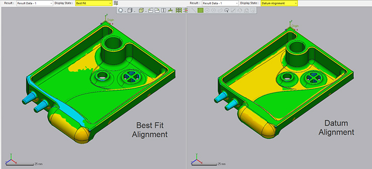
a. Once the scan data and the associated 3D CAD model are imported into Geomagic Control X, an initial alignment must be completed to orient the 3D scan (test data) to the CAD model (reference data). This initial alignment step is required prior to performing analysis, or more refined alignments. Best fit alignments are common prior to defining critical features that make up alignment datums that can be used for more robust alignment of data. Control X allows visualization of multiple alignment schemes at one time which can be extremely helpful to understanding part tolerances.
- Analysis
a. 3D Compare
Control X calculates the deviation between the XYZ points from the 3D measurement data and the 3D CAD models surface normal. An intuitive 3D Color Error Map is created and tolerances applied to visually show where the part is in and out of tolerance, and by exactly how much. These color maps can be represented in a number of customizable ways; below are two most common:- Go / No Go – green where in tolerance and red where out of tolerance
- Rainbow Color Gradient; Warm colors show where the part is outside upper tolerance zone, Green where part is within tolerance, Cooler colors show where the part is inside inner tolerance zone
Annotations can be dropped onto any surface to show exact deviation at any location.
b. Smart 3D Dimensioning
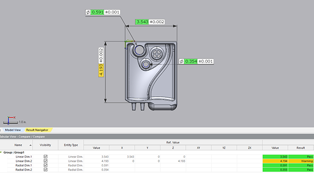
Control X has incorporated a dimensioning tool they call CAD Aware Dimensioning which allows for easy click and select dimensioning based on smart interpretation of selected features. Use the default dimension type or force these to match your dimension type – linear, angular, radial, etc.c. GD&T
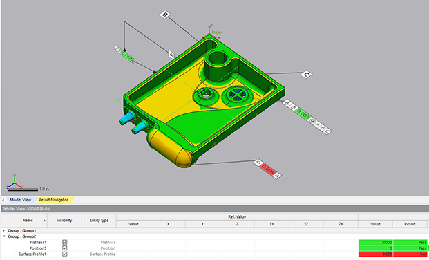
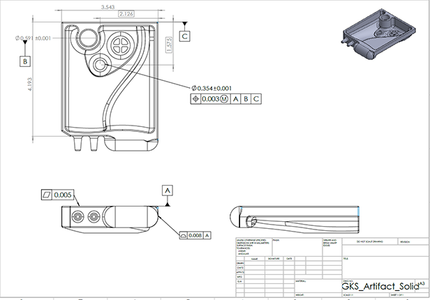
Control X implements Geometric Dimensioning and Tolerancing (GD&T) based on the ASME Y14.5M standard to define and communicate nominal geometry and the allowable variations of and between features.
d. 2D Dimensioning on Cross Section
Create a cross section using a datum, global reference plane or by offsetting from another face or plane. From this created section, use the easy dimensioning tools to click between lines and create distances, circles, angles, etc.

- Reporting
Once you’ve defined your measurement strategy, it’s time to think about how to communicate this information with internal and external customers & stakeholders. Geomagic Control X offers the ability to include visual and tabular results from any of the created entities from the inspection including reference data, measurement data, alignment details, 3D comparisons, GD&T and cross sectioning info. Easily customize the report by dragging and dropping reportable elements from the model manager. Export as PDF, 3D PDF, PPT in an automated way or export CSV and other formats for SPC software. Choose to report as little or as much as you’d like to communicate the critical measurements.
Benefits of 3D Scanning for Metrology Inspection
By combining CyberOptics XLP 3D laser scanning equipment with Geomagic Control X metrology software, engineers and metrologists have access to measurement and inspection tools that take away the guesswork and manual measuring found in traditional methods that can be inefficient for inspecting many parts. For over 30 years Laser Design Scanning Services has helped our customers save time and money focusing on:
- Appropriate and Effective Solutions
- Accurate and Precise Data
- Responsive Follow-through
- Customer Satisfaction
At Laser Design we are proud of the support we’ve provided to all of our customers, including Fortune 500 and leading manufacturers of electronic devices, cell phones, plastics, automobiles, medical devices, testing equipment, electrical equipment, aerospace equipment, and numerous educational institutions, art and natural history museums, as well as government agencies. Do you have a project in mind that requires 3D scanning for metrology inspection? Contact us today to learn more about how Laser Design can help you incorporate 3D scanning into your design and manufacturing process.
*Trademarks are owned by their respective companies.
