What is NURBS Surface Modeling?
This computerized 3D modeling method consists of applying digital contours and surface patches directly on 3D scan data to represent the geometry of the 3D scanned object mathematically. When searching for information on NURBS modeling, you will find that the acronym stands for Non-Uniform Rational Basis Splines (B-Splines). What you may not learn easily is that NURBS surface creation techniques are best applied when modeling complex and freeform shapes, as the final model represents the closest representation to the true/real geometry with greater accuracy and reduced labor time. For these types of objects, NURBS surface modeling provides an easier workflow to obtaining 3D CAD geometry then solid modeling as it is derived directly from the 3D scan data. Industrial CAD designers may prefer a solid model because of the way they can interact and manipulate the CAD geometries for prismatic part design, but NURBS surface modeling can be more beneficial than a solid model in many applications.
Advantages
Why choose NURBS as a modeling technique? It is more suited for parts that require higher accuracy and more of a “real” world situation that may include any defects, ejector marks, warp, etc. It has many strengths due to the flexibility. Although the NURBS technique is known for more organic shapes, it can be applied to many industries. Many native CAD users would find it beneficial because a NURBS model can be exported as a universal file such as STEP, IGES and Parasolid. Additionally, a number of 3D scan data processing software manufacturers have created simple and automated workflows to create the NURBS surface model from a 3D scan of an object. One such software that optimizes the NURBS creation process is Geomagic Design X. Integrated into this powerful software known for it’s parametric, history-based, reverse engineering capability, is a power tool to convert 3D scan data (triangulated mesh in formats like .stl, .ply, obj, etc.) to NURBS surface models using an Auto Surface routine in a 4 step process automatically! This quick and efficient way to generate a 3D model is outlined below to show how simple the process can be.
4 Easy Step Process
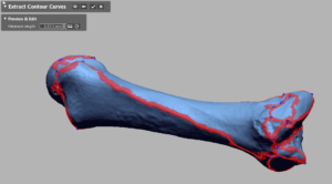
- Extract Contours : Geomagic Design X is able to automatically identify where logical 3D contours exist in a set of 3D scan data and digitally draw them onto the surface of the scan. These contours can be detected automatically, or the software will allow the designer to manually determine or modify these contours using control points.

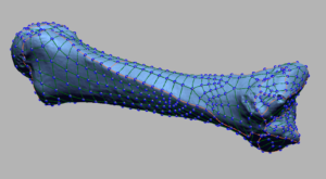
- Apply Patchwork : Using the automated or manually created 3D contours from step 1, Geomagic Design X software constructs a surface patch network over the entire 3D mesh data set. The main edges of the patchwork consist of the previously defined 3D contours and additional patches are included to allow for the surface to “wrap” over the mesh for the most accurate geometry representation.

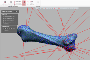
- Repair Patches: Within any automated or manual process, there exists the potential for error. Design X has integrated tools to automatically identify areas of poor geometry within the patchwork. This repair process can locate and resolve intersecting paths, poor patch angles, high degree corners and high deviation patches to ensure the highest quality and accuracy of NURBS surface is created.

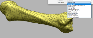
- Fit Surface Patches : after the repair process, the fit surface patches function creates the NURBS surfaces within the patch boundaries created in the first two steps. From here, 3D file export options exist in numerous industry wide standards such as IGES, STEP, ACIS and Parasolid.

Parametric vs NURBS Surface Modeling
Parametric 3D Modeling – This form of 3D modeling is based on 2D and 3D sketches which define an objects geometry mathematically. Incorporating techniques like lofts, sweeps and revolves to these sketches creates features that can be trimmed, extruded, offset, shelled, drafted, etc. to allow for creation of the desired 3D geometry. Parametric 3D CAD modeling is a history-based approach where all entities created can be accessed and edited. When the proper relationships and constraints are applied, editing a parametric model can be made very efficient as designers can make changes at pre-defined parameters. This type of 3D modeling is widely used when an object has prismatic shapes, but it can also be used for and objects with complex curvature. When geometry is tough to match with mathematically defined features, NURBS modeling is a great technique to explore. Geomagic Design X can create parametric 3D CAD models using the 3D scan as a reference/guide, and files can be Live Transferred to many native CAD packages like SOLIDWORKS, Creo, Catia, UGNX, Inventor, etc.
NURBS Surface Modeling – Non-uniform rational basis spline (NURBS) are shapes described by boundary curves and control points. When this technique is used on a raw scan data mesh, it provides you with great accuracy. Areas on the “bone” sample with higher edge profiles will allow the user to increase the number of patches/grids so the result is more accurate and aesthetically looks more realistic to the physical sample. A NURBS model does not have the same ability to modify as a parametric model, but it will provide a more accurate representation of the measurements from the 3D scan geometry. Imagine using 3D scan data of a human limb to create custom prosthetics. NURBS modeling provides the most simple and efficient workflow, while maintaining the highest accuracy to the 3D scan data. Parametric modeling of the limb geometry would be almost impossible to achieve similar accuracies to NURBS modeling.
Hybrid Modeling – when you have an object that includes a variety of prismatic and freeform shapes, a hybrid model may be the best approach. Feature based modeling can be used where a design-intent geometry is required for the design process, and the NURBS surfaces can be used to include the highest complexity curvature or freeform shapes. Below is a great example where the front end of an ATV was modeled using both prismatic and NURBS techniques resulting in a deliverable that allowed for aftermarket part design without the manual effort of parametrically modeling all features.
When you’re looking for reverse engineering services or software solutions, let Laser Design’s knowledgeable sales and technical staff guide you to the right solution based on over 30 years of 3D scanning and reverse engineering experience and leadership in this industry.
Helpful Links
FAQ – NURBS, Parametric Model
NURBS MODELING – Bike and Rider Project, Life-Enhancing Product for Partial Finger Amputees, Medical Applications
PARAMETRIC MODELING – Parametric CAD Model from 3D CT Scan Data
HYBRID MODELING – Accessory Fit on ATV
