 Turbine blades, made of curved vanes on a central rotating spindle, are everywhere. They whirl in everything from jet engines to wind-and water-power generators. They are even part of refrigeration processes and new tidal facilities that produce electricity. However, turbine blades of all sizes present a difficult challenge to their manufacturers: accurately producing and maintaining their complex free-form surfaces and convoluted shapes.
To begin with, manufacturers of turbine blades want to know whether their as-built parts match the original design intent. Issues of fit, safety, and aero- or hydro-dynamic flow can arise when the physicalblade does not conform to the correct design standards. Sometimes engineers want to reverse engineer an old blade with no CAD data, or redesign some aspect of the old blade into the new one. Subsequently, turbine blades must be maintained. Engineers and mechanics need to know the exact shape of the blade in order to restore in-service blades to spec and make sure molds and other manufacturing tooling stays true. In other words, precise, complete CAD models are critical to turbine blade manufacturers.
Contact measuring devices can only supply a partial set of landmark measurements. They cannot gather enough points to create a completely accurate surface profile of the blades’ irregular shapes. And a complete surface scan is exactly what is required to insure correctness of the shape over the whole span/surface of the blade.
Enter 3D Laser Scanning : Non-contact 3D laser scanning is a complete measurement method; it captures everything on the surface of an object, including free-form shapes and fine details. The technology works by projecting a line of laser light onto a surface while cameras continuously triangulate the changing distance and profile of the laser line as it sweeps along. The laser line passes back and forth over the area until the complete surface is captured. Irregular shapes are measured just as easily as prismatic ones, and they are instantaneously replicated digitally on-screen. The scanner measures very quickly, picking up tens of thousands of points per second, and generates huge numbers of data coordinates in a point cloud. After scanning from multiple perspectives, the point cloud data files are rotated into the same reference frame and assembled into an exact 360-degree 3D model of the scanned part.
The laser scanning process is highly automated which insures consistency and quality of the data obtained. Since it is a non-contact measuring method, there are no variations in practices or techniques from operator to operator, or pressure differences that may generate different readings in traditional touch-probe measurement. Laser scanning allows extremely consistent checking of parts by removing the human error factor.
With more than 25 years in the 3D scanning business, Laser Design Global Services has scanned a large number of turbine blades for a diverse group of customers and has come up with some specialized techniques to do it quickly and accurately, and obtain the best quality data. Some customers are interested in inspection and verification applications for new blades to make sure they meet design specifications. Others want to reverse engineer a turbine blade from an existing blade or use an existing blade as the basis for improvements or redesigning certain elements. Still other customers are looking to repair and maintain turbines blades and the molds and tooling used to make them that have been in use for some time.
Larry Carlberg, Service Bureau Manager of Laser Design-Minneapolis, has applied the advantages and benefits of 3D laser scanning to the hundreds of turbine blade projects he has performed. “Having the right system and software are essential in creating accurate results in a short time,”he explained. “Laser Design has both the equipment and the software, and also the experienced personnel, to produce the desired scan results.”
Inspection
 Because high-speed laser scanning captures the entire shape of an object, not just select features, the whole part is scanned, instead of a small percentage of points. The entire as-built part can be compared to the complete CAD design to generate a comprehensive error report of discrepancies. First articles can quickly be inspected before going into full production to correct problems, saving time and
lowering the scrap rate.
A blade may have hundreds of dimensions which are all in spec, but it also has features that are not dimensions because they are not individually measurable. Out-of-spec problems may occur within these “feature” areas and may not be detected. Complex computer-designed free-form blade shapes are hard to measure traditionally and the results are incomplete. Laser scanning verifies all of the geometry to create a fully qualified part.
Laser scanning also reduces the discrepancy between the as-designed part and the as-built part. A conventional first article drawing may have several hundred dimensions, with only two dimensions out of tolerance. Tremendous time and man-power resources could be wasted in measuring the whole part with conventional touch-scanning methods trying to determine where those two problem areas are located. Using original scan data to create an inspection report shows how every physical dimension measures against the CAD model.
Laser Design’ library of software includes Geomagic Qualify with its special blade module (called “Blade”) which greatly expedites turbine inspections. The software recognizes that complex-shaped turbine blades need millions of points of scan data to adequately define their contours. Performing this volume of measurements would be difficu lt if not impossible to accomplish using a CMM. Laser scanning provides the means for gathering the voluminous point cloud data for turbine blade applications.
Carlberg explained Laser Design’ unique method for scanning turbine blades: “In industry, a theoretical nest is used to fixture blades at specific points for inspection. These points are called ‘line target datums.’ The specialized blade software we use allows transposition of theoretical points collected with no reference to position key theoretical datums. We can localize the line target datums to lock down location and position XYZ.”
“When a turbine blade is machined, it is very important that it is held to target datums which are used to inspect the blade. The CAD model of the blade butts up to only one reference datum because of the curved shape of the blade. When we scan a blade, we ask the manufacturer for the target datum and then align the scan data to it after the fact. When we compare the scan data to the CAD model, all the areas where the part is incorrect are exposed. This method sets Laser Design apart. It is fast, accurate, and very revealing.”
Turbines of any size can be laser scanned. Laser Design has a range of scanner sizes from a small desktop unit to a portable large-scale scanner that allows scanning of huge power generator and aero-engine blades that are fixed to a main rotor. “Our scanning method has been extremely successful with many of the large-scale projects we have performed,” added Carlberg. “The inspection reports show deviations from the CAD model with color coding, which makes the discrepancies obvious.”
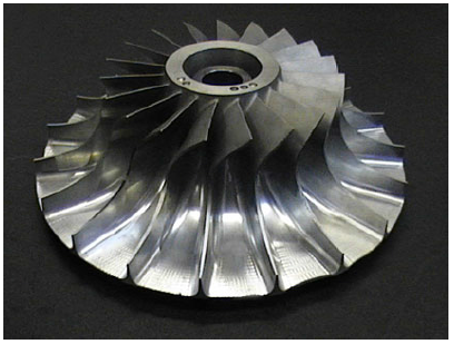
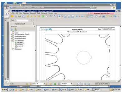
Laser Design has also laser scanned impeller parts, which has the turbine blade rotor inside some type of conduit to increase the pressure and flow of a fluid. The blades of an impeller are made in one single casting, so it has complex contours of 20 or more blade features around the central rotating core. With so much complexity in the free-form shapes on so many blades, none of whom are exactly the same, measuring an impeller manually could take as long as several weeks. Laser scanning reduces the time spent to just a few hours and produces more complete and accurate results, as shown in a color-coded deviation report.
Reverse Engineering
 As with many older parts, extant turbine blades may not have CAD data from which to manufacture replacements. Or perhaps an engineer wants to use an existing blade as the basis for improvements or redesigning certain features. High-speed laser scanning makes reverse engineering physical blades practical and possible because it captures the entire shape of an object, not just select features like in traditional measuring methods.
Laser scanning excels at capturing complicated geometric aspects of parts, such as the irregular free-form curves on a turbine blade. When evaluating a part that will be used in production, automated capability studies can be run, which set defined parameters of tolerance intervals to be applied to all the samples examined. Many checks including form analysis, optimization, tool wear, and trend analysis can be conducted on the newly gathered CAD data of the blades.
Laser Design recently scanned a complex many-bladed impeller for a small engine manufacturer that wanted to create new tooling for it. The deliverable was a solid model of the entire impeller: blades, spindle, and base profile. Carlberg explained, “We used Laser Design’s Surveyor WS-2030 system with a high-accuracy SLP-400 laser probe and the Renishaw PH-10 indexing head to get the best views of the part. The scan required two set-ups, one from the top side and one from the flip side, to get as much of the geometry as possible. Difficult areas included the curved shapes between the vanes because of the limited line of sight for the laser probe and the depth of the spaces. In order to successfully capture all the geometry we scanned from multiple perspectives for each vane. Scanning time was approximately 3 hours; data editing time was 1 hour with Geomagic Studio software; modeling time was about 7 hours with Rapid form software.
In order to reverse engineer a turbine blade or impeller it is important to understand what the customer requires,” commented Carlberg. “A perfect CAD model is necessary for machining and to determine mold flow or use in other analyses. Impeller blades must be very consistent in weight, size, and geometry or they will vibrate and impede performance of the part. Laser scanning makes this possible to attain with reverse engineering.”
Laser scanning is advantageous to many manufacturers with complex legacy parts, turbine blades being a prime example. As-is geometry for re-design or re-manufacture warrants a thorough collection of the complete data set.
Repair and Maintenance
 Inspection reveals an imperfect part when compared to a perfect model. Imperfections can be from the machine operation or wear from use. Not only the turbine blades, but the molds and castings that create them will at some point need maintenance and repair. Turbine blades in particular are subject to damage and wear, and non-contact laser scanning excels at capturing their irregular free-form contours and those of their tooling.
Inspection reveals an imperfect part when compared to a perfect model. Imperfections can be from the machine operation or wear from use. Not only the turbine blades, but the molds and castings that create them will at some point need maintenance and repair. Turbine blades in particular are subject to damage and wear, and non-contact laser scanning excels at capturing their irregular free-form contours and those of their tooling.
Non-contact laser scanning can be used to validate tooling, even when no CAD model exists. Manufacturing processes require tooling to create parts and certain features of parts. Injection molding tools and castings are often validated with laser scanning, because it is so thorough. New or used tools may also be scanned for wear or to predict wear, and aid in repairing, maintaining, or changing out tools to keep them dimensionally correct.
Legacy turbine blades sometimes have no CAD models, or the mold has been manually modified over time to make improvements and corrections. Either the altered mold or the part created from it, or both can be laser scanned to update incorrect or obsolete CAD models to the true representation of the as-built object. Up-to-date documentation is a valuable asset for manufacturers, and essential in many regulated industries which use turbine blades such as aerospace.
When parts are repaired or refurbished, a 3D laser scan provides data to compare with the CAD model to validate repairs. For example, according to Carlberg, many times a broken or gouged out part of a turbine blade is repaired with a weldment. However the material may extend beyond what is needed to restore the lost geometry. The scan file of the repaired area shows precisely what needs to be milled off to obtain the original shape.
Laser scanning can also record and help to predict lifetime wear and tear patterns, as well as troubleshoot in a failure scenario. Scanning worn turbine blades can yield information of interest to engineers in terms of wear patterns and life expectancies of the part. This analysis, in turn, can improve safety by predicting inspection and replacement schedules more accurately.
Benefits of Laser Scanning Services
No matter what the application, scanning turbine blades with a 3D laser scanning system can quickly generate extremely accurate CAD data of the entire blade or assembly. Laser Design’s experts can assist with any type of project. Inspection reports provide at-a-glance feedback on the parts’ tolerances, making go/no-go decisions automatic. Laser scanning can create CAD data for legacy blades which have none, so that they can be reverse engineered, or the data can be used to revise specific features. Maintaining and repairing blades and their tooling, molds, and castings is just as important as a quality manufacturing process. 3D laser scanning can substantiate that repairs are correct, ensuring the safety of turbine engines, whether they are used in aircraft, traditional power-generating plants, or developing new greener power sources.
